Ask Latest Price
Active Member
9 Years

Neteb Arcade
Our company website:www.netebarcade.com


Add to Cart
Video:https://youtu.be/W-UUQQMAa8M https://youtu.be/f4pYHkuR6w4
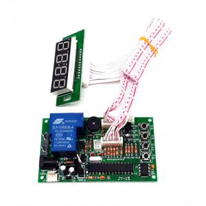
Description
| Input Voltage | DC+12V |
| Standby | Display shows:00:00, rely: Normal Open (NO) |
| Accumulated time | Yes, add time if receive signals again when time is running |
| Max current load | 15A |
| How it works | |
| Mode 1 | Time runs down after receive signals-> Display shows remaining time and supply power to device-> it cuts off power after time runs out |
| Mode 2 (Connect a button) | Display shows remaining time after receive signals-> push button start-> time runs down and supply power to device-> it cuts off power after time runs out |
| Pause (connect a button) | Push button pause: it cuts off power when pause, display shows remaining time. Re-supply power after push button pause again |
| Operating Mode | Please reference to page 2 |
| Connection Example | Please reference to page 2 |
Connection and Position

|
|
Setting
Please follow CODE ON DISPLAY and use button "S1" and "S2" to set up number
PAGE-2
Please follow table to set up operating function:
| Function | Code on Display | Description | |
| A | B | ||
| Running Time | 01 | 01 | Time runs down without pressing button |
| 02 | Time runs down by pressing button | ||
| Time Type | 02 | 03 | MINUTE: SECOND |
| 04 | HOUR: MINUTE | ||
| Memory | 03 | 05 | Yes: Remaining time keep running after power off and on |
| 06 | No: Standby power off and on | ||
| Back to standby | 04 | 1-30 | user has no action after push buttons or receive signals in setting time |
| Default: 01-03: Bold and base line. 04: not use the function. | |||
Connection Example
comparison
Main board
Display